- 您现在的位置:买卖IC网 > Sheet目录473 > MAX2620EVKIT (Maxim Integrated)EVAL KIT MAX2620
�� �
�
�10MHz� to� 1050MHz� Integrated�
�RF� Oscillator� with� Buffered� Outputs�
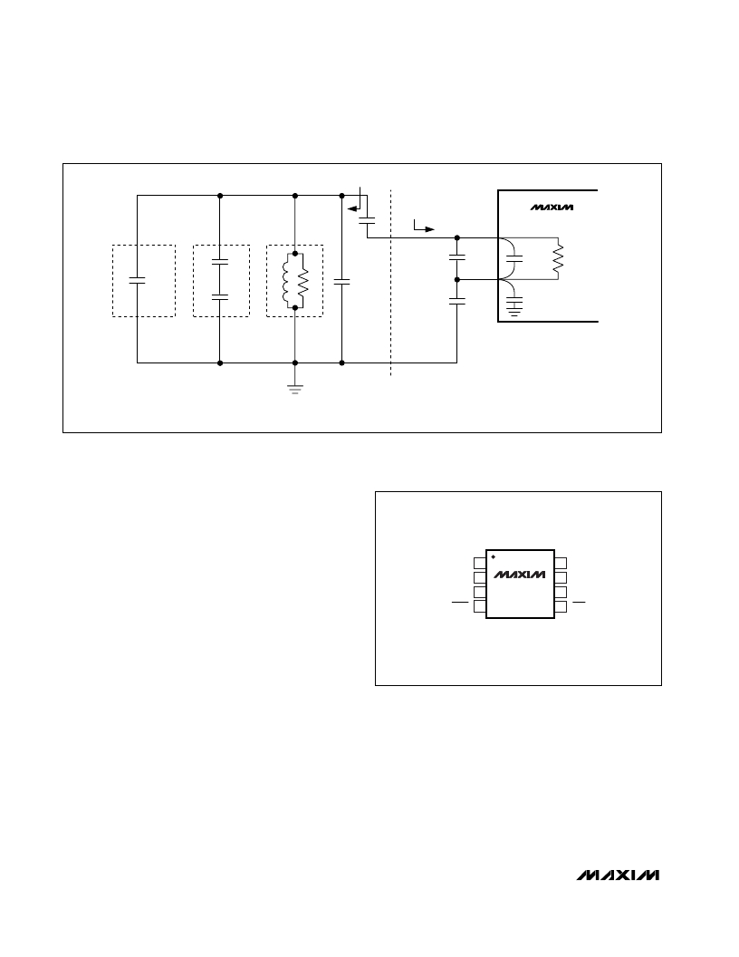
�R� S� +� jX� S�
�TEST� PORT�
�MEASUREMENT�
�C5�
�(FIGURE� 1)�
�MAX2620�
�C17�
�C3�
�C� 03�
�2.4pF�
�R� n�
�C� STRAY�
�PC� BOARD�
�PARASITICS�
�C� D1�
�VARACTOR+�
�COUPLING�
�L1�
�R� p�
�INDUCTOR�
�OR�
�C6�
�C4�
�C� 04�
�2.4pF�
�CERAMIC�
�RESONATOR�
�RESONANT� TANK� MODEL�
�Figure� 5.� Electrical� Model� of� MAX2620� Circuit�
�resonators� or� high-Q� inductors.� Also,� keep� C5� and� C17�
�(see� the� Typical� Operating� Circuit� )� as� small� a� value� as�
�possible� while� still� maintaining� desired� frequency� and�
�tuning� range� to� maximize� loaded� Q.�
�There� are� many� good� references� on� the� topic� of� oscilla-�
�tor� design.� An� excellent� reference� is� “The� Oscillator�
�MAX2620� PACKAGE� MODEL�
�__________________Pin� Configuration�
�TOP� VIEW�
�as� a� Reflection� Amplifier,� an� Intuitive� Approach� to�
�Oscillator� Design,� ”� by� John� W.� Boyles,� Microwave�
�Journal� ,� June� 1986,� pp.� 83–98.�
�Output� Matching� Configuration�
�Both� of� the� MAX2620’s� outputs� (OUT� and� OUT� )� are�
�V� CC� 1� 1�
�TANK� 2�
�FDBK� 3�
�SHDN� 4�
�MAX2620�
�8�
�7�
�6�
�5�
�OUT�
�V� CC� 2�
�GND�
�OUT�
�open� collectors.� They� need� to� be� pulled� up� to� the� sup-�
�ply� by� external� components.� An� easy� approach� to� this�
�pull-up� is� a� resistor.� A� 50� ?� resistor� value� would� inher-�
�ently� match� the� output� to� a� 50� ?� system.� The� Typical�
�Operating� Circuit� shows� OUT� configured� this� way.�
�Alternatively,� a� choke� pullup� (Figure� 1),� yields� greater�
�output� power� (approximately� -8dBm� at� 900MHz).�
�When� maximum� power� is� required,� use� an� inductor� as�
�the� supply� pull-up,� and� match� the� inductor’s� output�
�impedance� to� the� desired� system� impedance.� Table� 1�
�in� the� Typical� Operating� Characteristics� shows� recom-�
�mended� load� impedance� presented� to� OUT� and� OUT�
�μ� MAX�
�for� maximum� power� transfer.� Using� this� data� and� stan-�
�dard� matching-network� synthesis� techniques,� a� match-�
�ing� network� can� be� constructed� that� will� optimize� power�
�output� into� most� load� impedances.� The� value� of� the�
�inductor� used� for� pullup� should� be� used� in� the� synthe-�
�sis� of� the� matching� network.�
�10�
�______________________________________________________________________________________�
�发布紧急采购,3分钟左右您将得到回复。
相关PDF资料
MAX2623EVKIT
EVAL KIT
MAX2632EUK+T
IC AMP 3V VHF/MICROWAVE SOT23-5
MAX2634EVKIT+
KIT EVAL FOR MAX2634 AUTO AMP
MAX2641EVKIT
EVAL KIT MAX2640, MAX2641
MAX2643EVKIT
EVAL KIT MAX2642, MAX2643
MAX2644EVKIT
EVAL KIT MAX2644
MAX2645EVKIT+
EVAL KIT MAX2645
MAX2650EUS+T
IC AMP DC TO MICRO LN SOT143-4
相关代理商/技术参数
MAX2622EUA
功能描述:VCO振荡器 855MHz - 881MHz Mono V Ctrld Osc RoHS:否 制造商:Exar 封装 / 箱体:SOIC-14 频率:300 kHz 负载电容: 封装:Reel 电源电压:4.5 V to 20 V 尺寸:4 mm W x 8.75 mm L x 1.75 mm H 最小工作温度:0 C 最大工作温度:+ 70 C
MAX2622EUA+
功能描述:VCO振荡器 855MHz - 881MHz Mono V Ctrld Osc RoHS:否 制造商:Exar 封装 / 箱体:SOIC-14 频率:300 kHz 负载电容: 封装:Reel 电源电压:4.5 V to 20 V 尺寸:4 mm W x 8.75 mm L x 1.75 mm H 最小工作温度:0 C 最大工作温度:+ 70 C
MAX2622EUA+T
功能描述:VCO振荡器 855MHz - 881MHz Mono V Ctrld Osc RoHS:否 制造商:Exar 封装 / 箱体:SOIC-14 频率:300 kHz 负载电容: 封装:Reel 电源电压:4.5 V to 20 V 尺寸:4 mm W x 8.75 mm L x 1.75 mm H 最小工作温度:0 C 最大工作温度:+ 70 C
MAX2622EUA-T
功能描述:VCO振荡器 855MHz - 881MHz Mono V Ctrld Osc RoHS:否 制造商:Exar 封装 / 箱体:SOIC-14 频率:300 kHz 负载电容: 封装:Reel 电源电压:4.5 V to 20 V 尺寸:4 mm W x 8.75 mm L x 1.75 mm H 最小工作温度:0 C 最大工作温度:+ 70 C
MAX2622EVKIT
功能描述:时钟和定时器开发工具 MAX2622 Eval Kit RoHS:否 制造商:Texas Instruments 产品:Evaluation Modules 类型:Clock Conditioners 工具用于评估:LMK04100B 频率:122.8 MHz 工作电源电压:3.3 V
MAX2623EUA
功能描述:VCO振荡器 855MHz - 950MHz Mono V Ctrld Osc RoHS:否 制造商:Exar 封装 / 箱体:SOIC-14 频率:300 kHz 负载电容: 封装:Reel 电源电压:4.5 V to 20 V 尺寸:4 mm W x 8.75 mm L x 1.75 mm H 最小工作温度:0 C 最大工作温度:+ 70 C
MAX2623EUA+
功能描述:VCO振荡器 855MHz - 950MHz Mono V Ctrld Osc RoHS:否 制造商:Exar 封装 / 箱体:SOIC-14 频率:300 kHz 负载电容: 封装:Reel 电源电压:4.5 V to 20 V 尺寸:4 mm W x 8.75 mm L x 1.75 mm H 最小工作温度:0 C 最大工作温度:+ 70 C
MAX2623EUA+T
功能描述:VCO振荡器 855MHz - 950MHz Mono V Ctrld Osc RoHS:否 制造商:Exar 封装 / 箱体:SOIC-14 频率:300 kHz 负载电容: 封装:Reel 电源电压:4.5 V to 20 V 尺寸:4 mm W x 8.75 mm L x 1.75 mm H 最小工作温度:0 C 最大工作温度:+ 70 C